Shader
Render pipeline
Main steps
In the 3D industry (Gaming, Animation, Architecture, CAD…) a Render Pipeline is a sequence of processing steps executed one after the other to produce the 2D image displayed on the screen. For example, Unity’s rendering pipelines, all follow a similar structure:
Culling - The system removes objects that the camera do not see to save computation time
Batching - Objects with same material are grouped together to be processed more efficiently
Shadow Pass - The system calculates where shadows should appear based on light sources
Geometry Pass - The shapes of all objects are rasterized without illumination and color
Lighting Pass - Lights are applied to objects to make them look realistic
Transparency - See-through objects like glass are drawn
Post-Processing - Effects like glow or blur are added
Final Image Display - Everything is combined into a single image and sent to the monitor for display
Check
First, check the current pipeline used by Unity:
Select Menu > Edit > Project Settings > Graphics
Find the name of the selected Pipeline
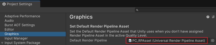
At this step, you should see URP.
A bit of history
In 2025, three render pipelines are available in Unity 6:
Pipeline |
Year |
Recommended Use |
Pros / Cons |
|---|---|---|---|
Built-In |
2005 |
Simple projects |
Easy to use, not flexible, not very efficient |
URP |
2019 |
Mobile, Web, VR |
Good performance, more flexible, slightly complex |
HDRP |
2019 |
High-end PCs, consoles |
High quality, very complex, for experienced devs |
URP is intended to replace the Built-In pipeline which is going to become deprecated. In the long run, HDRP may merge with URP, resulting in a single, cross-platform, and highly customizable render pipeline.
Note
While browsing the Asset Store, check the compatibility of the assets with your render pipeline. If no information is given, the asset package is likely quite old and only compatible with the Built-In Pipeline.
Shaders & Materials
Definition
A shader can be seen as a mathematical function that computes how light interacts with a surface. It also includes additional parameters that allow you to adjust certain effects, such as glossiness. There are many shaders available, some of which allow for very different visual styles, like cartoon rendering or water effects. A shader can also be an enhanced version of an existing one, offering more parameters and possibilities. A shader can be compared to an artist’s brush: its size and shape determine what kinds of effects can be created more easily.
Every material is based on a shader. By assigning values to the shader’s inputs — such as color, texture, or glossiness — the shader is configured to reproduce a specific material, like skin, glossy plastic, or natural wood. Even though multiple materials can share the same shader, they can look completely different on screen!
Shader incompatibility
When importing assets from other projects, some of their shaders may not be compatible with your render pipeline. In that case, the object will show up bright pink as a warning. »
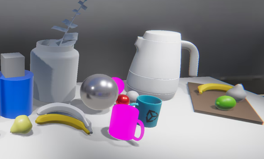
In such a case, you need to repair the broken shader.
Lit / Unlit
In Unity, shaders with « Lit » in their name react to scene lighting and are designed for realistic materials. Shaders with « Unlit » in their name ignore lighting, making them ideal for UI, effects, or stylized visuals.
Type |
Reacts to lighting? |
Typical usage |
|---|---|---|
Lit Shader |
✅ Yes |
Realistic rendering, immersive 3D |
Unlit Shader |
❌ No |
UI, effects, stylized graphics |
URP-Lit shader
The URP-Lit shader in Unity’s Universal Render Pipeline (URP) is a physically-based shader that provides a balance between performance and visual quality. Below is a breakdown of its key parameters and how they affect rendering.
Scene Setup
Navigate to Assets > Scenes
Create a new folder named « Rendering »
Inside this folder, create a new scene called « LitTest »
Double click to open it
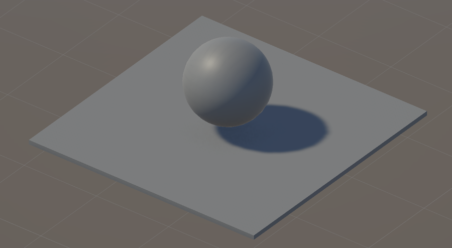
Create a floor using a Cube
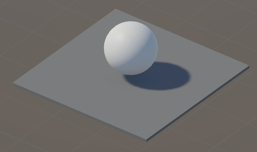
Create a Sphere and push it upwards
Notice that the sphere primitive had by default a material with gray color
The Sphere is casting a shadow on the floor
In the Rendering folder, right click and select Create > Material
Rename the new material “Ball_Mat”
Drag and drop this material onto the ball
The ball becomes white
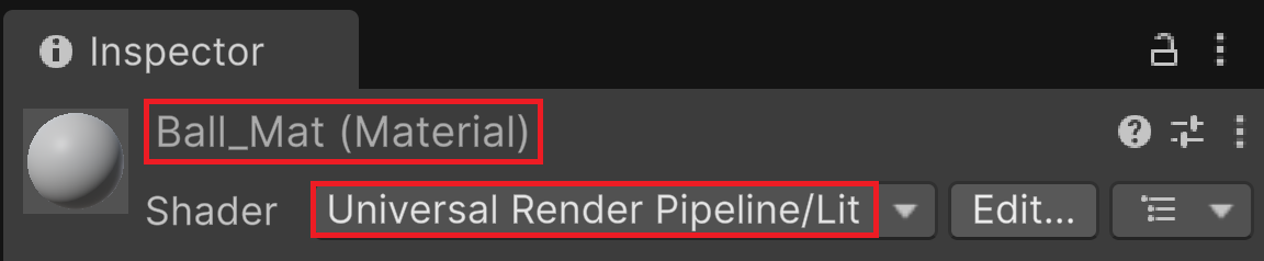
In the Inspector, with the material selected
Notice that the name of the new material is « Ball_Mat »
Notice that this new material is based on the URP/Lit shader by default
Basic Inputs
These three parameters define the base appearance of the material:
Base Map: main color
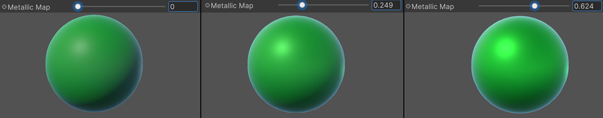
Metallic: Controls how metallic the material appears. A value of 1 makes it fully metallic, while 0 makes it non-metallic
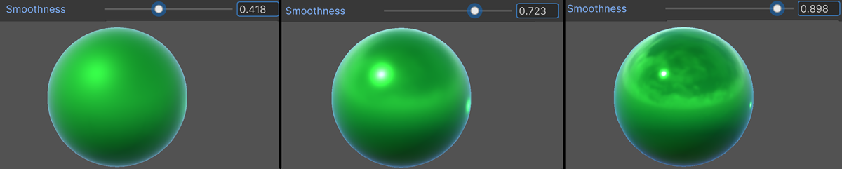
Smoothness: Controls how reflective and smooth the surface appears. A higher value results in sharper reflections
We test these parameters:
In the Inspector, look for the Surface Inputs section:
For the Base Map property, click the white color swatch to choose a new color
Adjust the slider named Metallic Map to make the object more or less shiny
Remember that you have a preview of the result at the bottom of the window :
Adjust the Smoothness slider to sharpen or to blur reflections on the material :
Advanced inputs
When we speak of a « map », you can consider that we are also referring to a texture. We say « map » to describe a texture with data: normals, height, reflectivity… The term « texture » is usually reserved for visuals like color.
Color texture
Instead of a solid color, we can select a texture to paint the surface of an object.
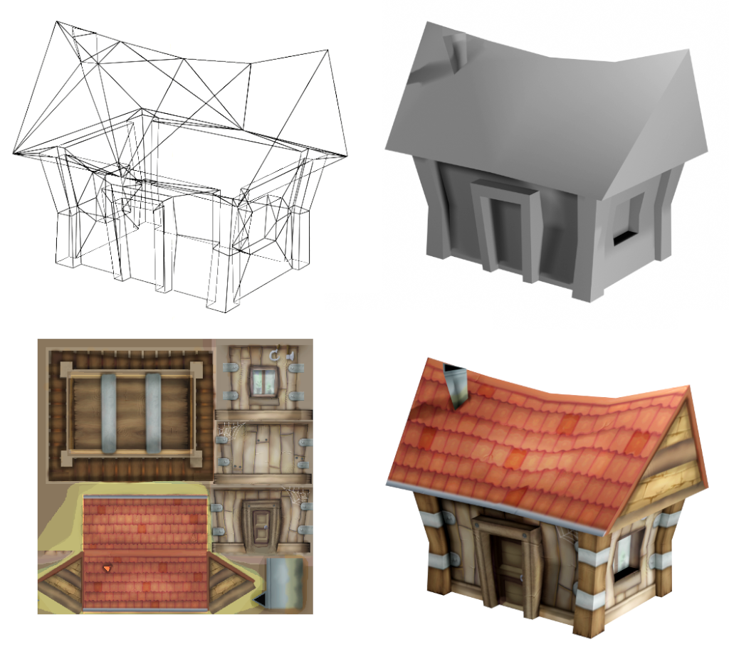
A mesh is a set of vertices, edges, and triangles that defines the surface of a 3D object. As an example, the top-left image shows the mesh of a 3D house.
The top-right image displays the shaded version of this mesh, without any color.
In the bottom-left image, you can see the color texture, which includes the drawing of the house’s walls and roof. To apply this 2D texture to the 3D mesh, we use something called UV coordinates: each vertex of the mesh is linked to a point on the color texture. UVs are created by 3D artists using specialized software like Blender or Maya, and cannot be edited directly in Unity.
When the mesh is displayed on screen, the texture and geometry are combined thanks to the UVs. The result is shown in the bottom-right image.
Normal map
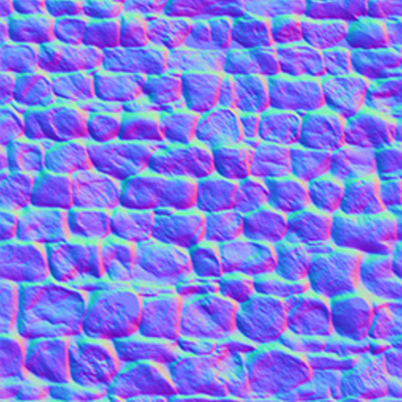
Normal map create the illusion of surface details (depth, bump, scratch) without modifying the initial geometry of the object.
Here is a normal map, with its characteristic pink and cyan colors:
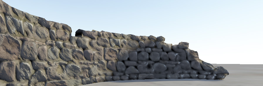
A stone wall with no bumpmap effect. The wall seems flat with no detail:
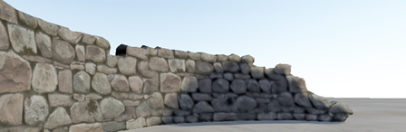
The same geometric mesh but with bumpmapping applied:
Note
It’s a trompe-l’œil effect! The geometry never changed: if you look at the edges of the walls, they are exactly the same. However, the addition of light and shadow effects enhances the illusion of depth.
Note
Bump maps have another advantage. First, they make the object look better; second, they allow us to reduce the number of vertices while still maintaining a high-quality appearance — ideal for low-end hardware
Occlusion map
An occlusion map defines areas that receive less indirect light (light emitted by objects, not by a light source).
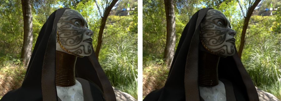
Before and after applying an occlusion map. The areas that are partially obscured, particularly in the folds of fabric around the neck, are lit too brightly on the left. After the ambient occlusion map is assigned, these areas are no longer lit by the green ambient light from the surrounding wooded environment. This map can be computed using occlusion algorithm.
Emission map
An emission map makes the material emit light, useful for neon signs, glowing eyes, etc
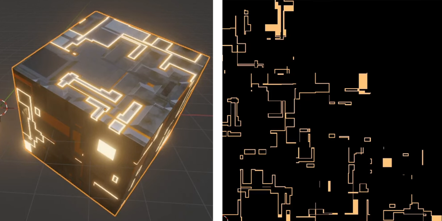
On the right, an emissive map and on the left the corresponding emission effect
Avertissement
Height maps, normal maps, and emission maps are typically created by graphic artists — you won’t need to design them yourself! However, it’s important to remember their names and what they’re used for. When importing assets, these textures are usually scattered throughout the ZIP file, and you’ll need to correctly assign them in the Lit Shader to ensure proper rendering.
Production
Pro texture
High-quality textures are made by 3D artists. They create images like normal or height maps to make surfaces look realistic. These assets are often sold or shared online for use in games and visual projects. Here’s an example of a professional website 3DTextures
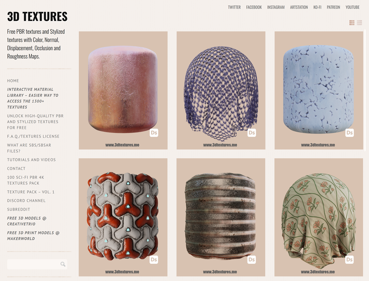
This website provides free textures that we’ll be working with. Please download the following zip:
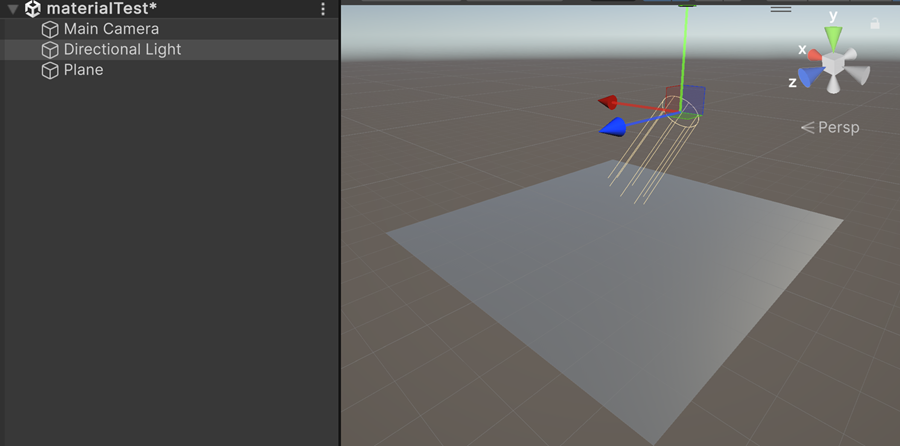
Scene Setup
Navigate to Assets > Scenes > Rendering
Create a new scene named « mat test » and double click to open it
Create a Plane (we don’t usually use it)
Select the Directional Light and move it near the plane
Inside this folder, create a subfolder named « WallStone »
Uncompress the zip file and paste all the textures in this new folder
In the same folder, right click and select: Create > Material
Name this new material: « WallStone »
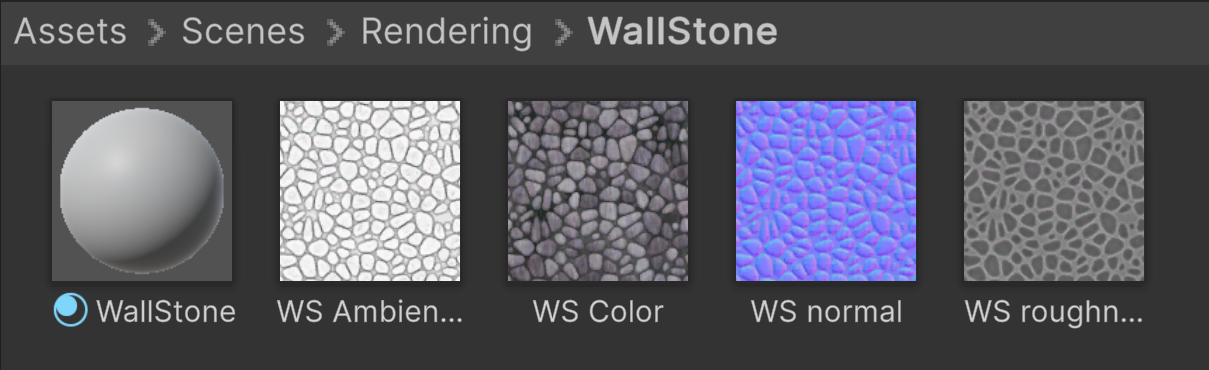
Drag and drop this new material onto the plane, it should turn white
In the asset folder, select the WallStone material
Color Texture
Drag and drop the WS Color texture into the square on the left of the Base Map parameter:
Inspect the plane: the color texture is present and the image looks fine, but it appears mostly flat
Bump map
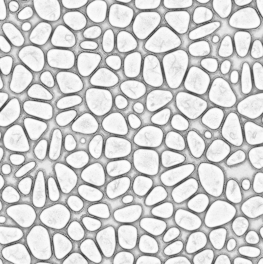
Drag and drop the WS normal texture into the square on the left of the Normal map parameter.
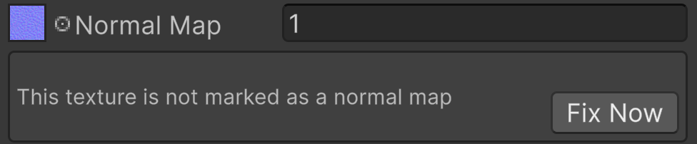
Click on the Fix Now button to automatically tag the texture as a normal map
To the right of the Normal Map, there is a value that allows you to adjust the intensity of the effect. Try the value 10:
The different stones appear to have gained volume, and the wall has some depth. However, when viewed from the side, it becomes clear that it’s just an optical illusion: the plane is still completely flat!
Try other values like: 0, 2, 4, 8, 16
Ambiant occlusion
The stones can receive light from other objects around them, but the cement between the stones receives less light because the surrounding stones block it. The WS Ambient Occlusion texture is black where indirect light has no effect, and white where the object is fully exposed to it:
Drag and drop the WS Ambient Occlusion texture into the square on the left of the Occlusion map parameter.
The AO map immediately darkens the areas around the edges of the stones, giving the scene a more realistic look