Modeling
Basic modeling
It is not always easy to find graphic assets that match your needs. Therefore, you should at least know how to create simple shapes to enhance your 3D demos. The first and simplest approach is to model the elements of your game using a cubic shape or a sphere. This is the basic technique that everyone should know.
For example, if you want to model a pickup pickup:
Check on internet vehicle dimensions: « pickup pickup vehicle dimensions »
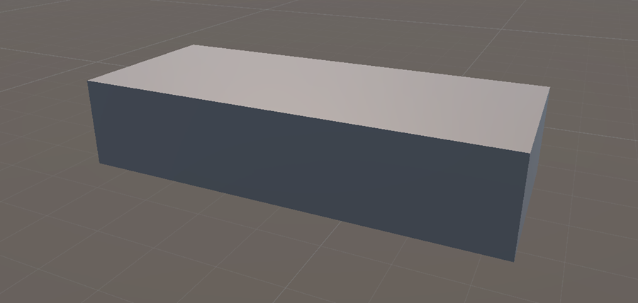
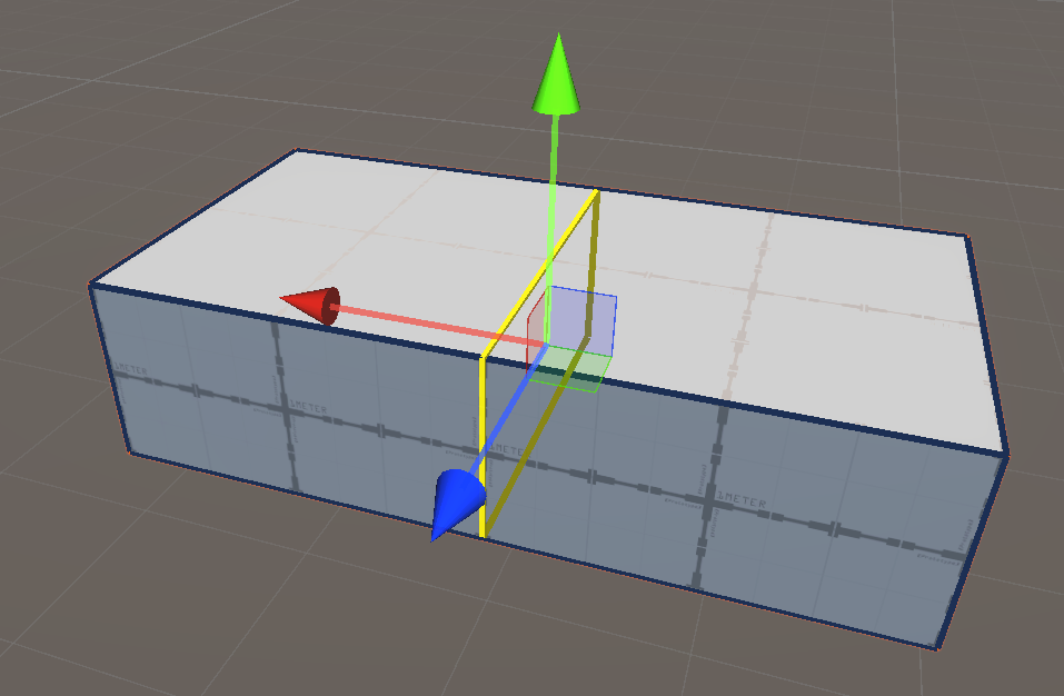
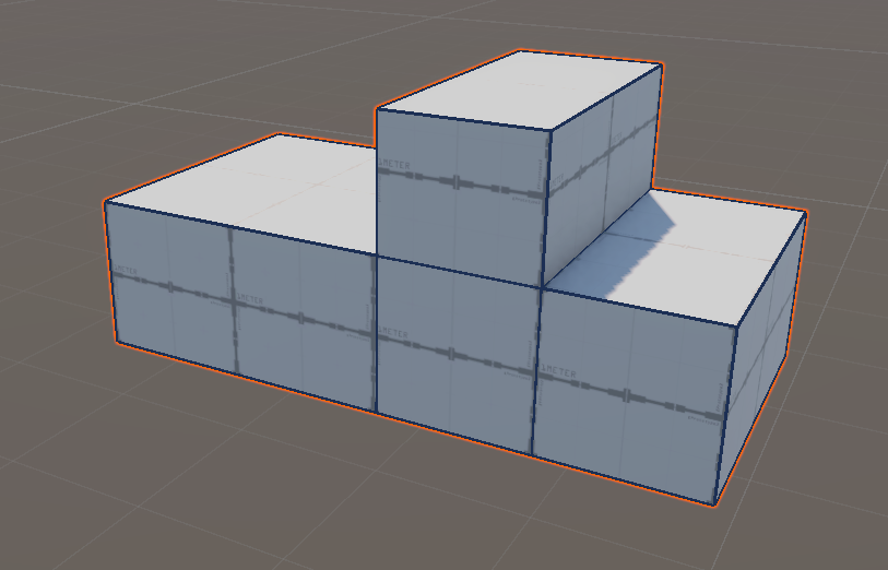
Create a 3D Cube
In the Inspector, in the scale values, enter 6, 2 and 2.5 (distances are in meters)
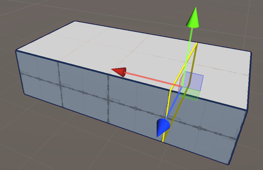
Duplicate this cube (CTRL-D)
Move this cube upward so that it is placed above the base
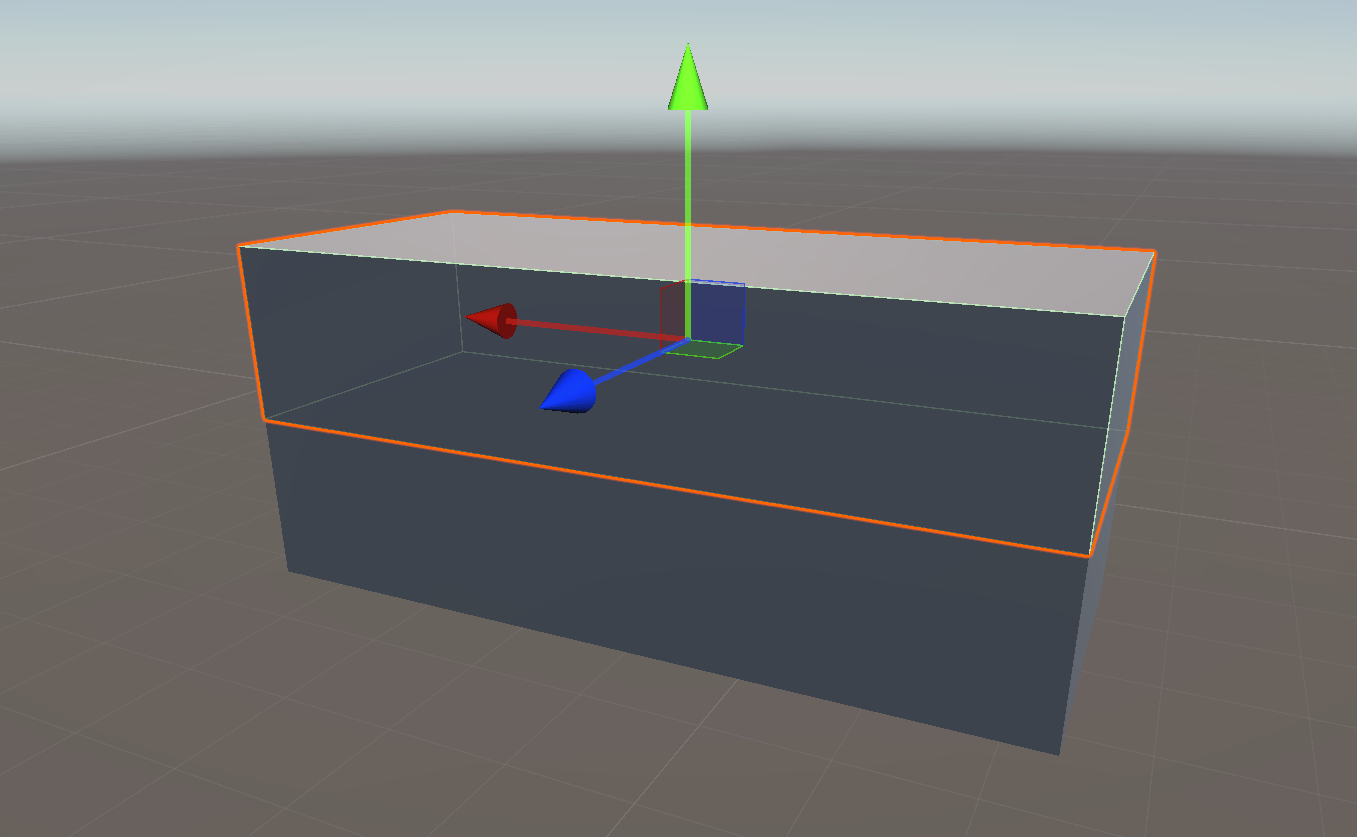
Change its X scale value to 1.5
Move this cube to obtain a ratio 1/2 1/4 1/4
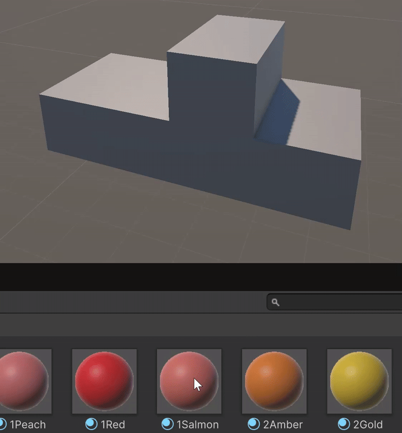
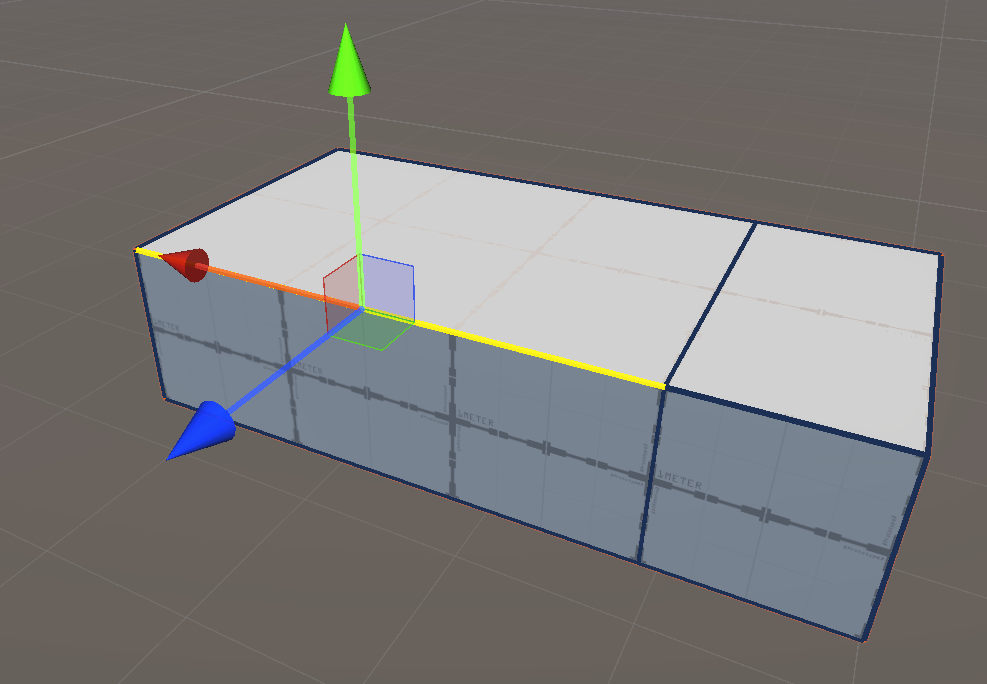
In the Assets folder, go to SolidColorMaterials folder
Drag and drop a material to color our two cubes
Select the two cubes (SHIFT+Click)
Use CTRL+SHIFT+G to group them
In the hierarchy windows, click on the newly created object and rename it Pickup
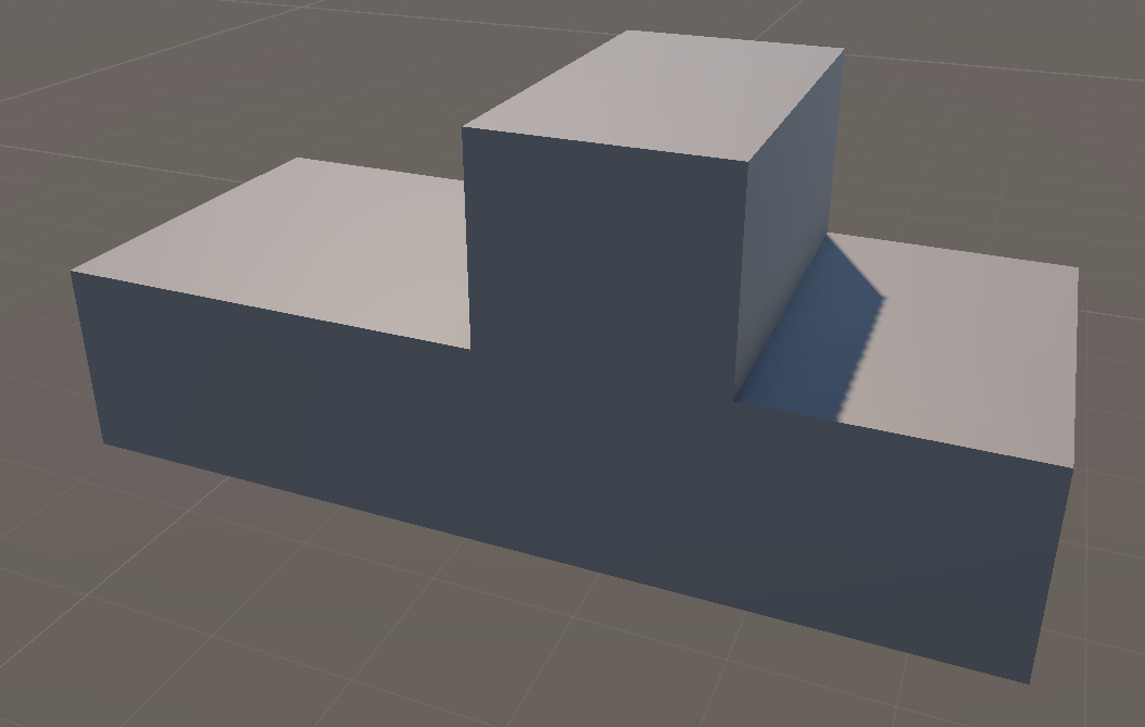
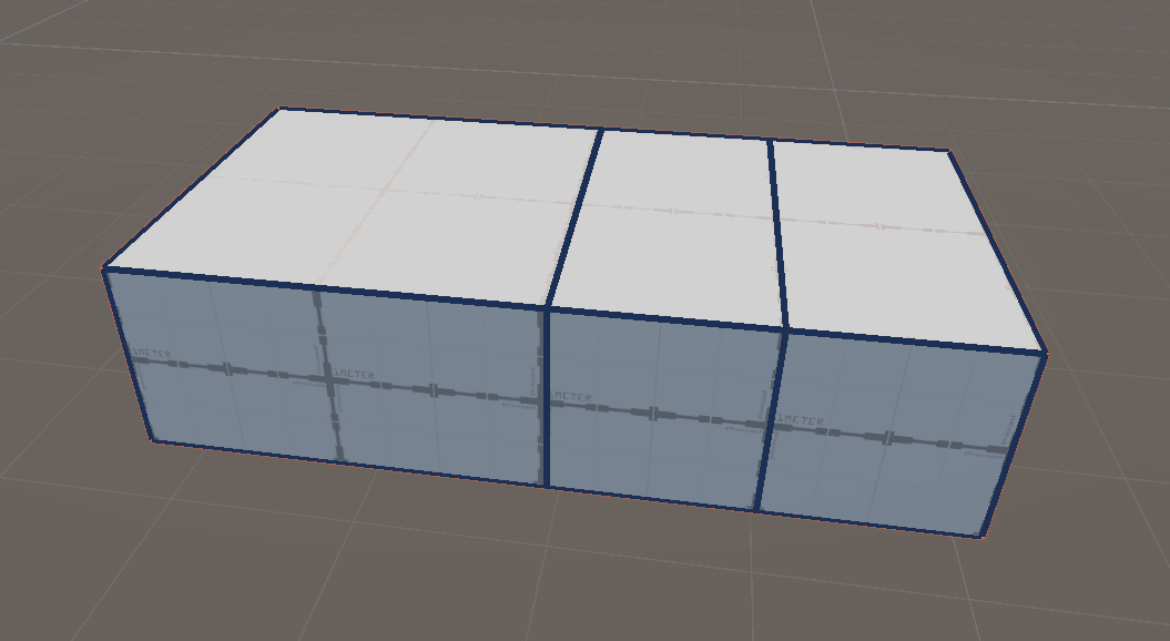
Here is our final result:
Avertissement
You should at least reach this level of modeling for your project. It is simple, effective, and allows for a good understanding of the objects in the scene.
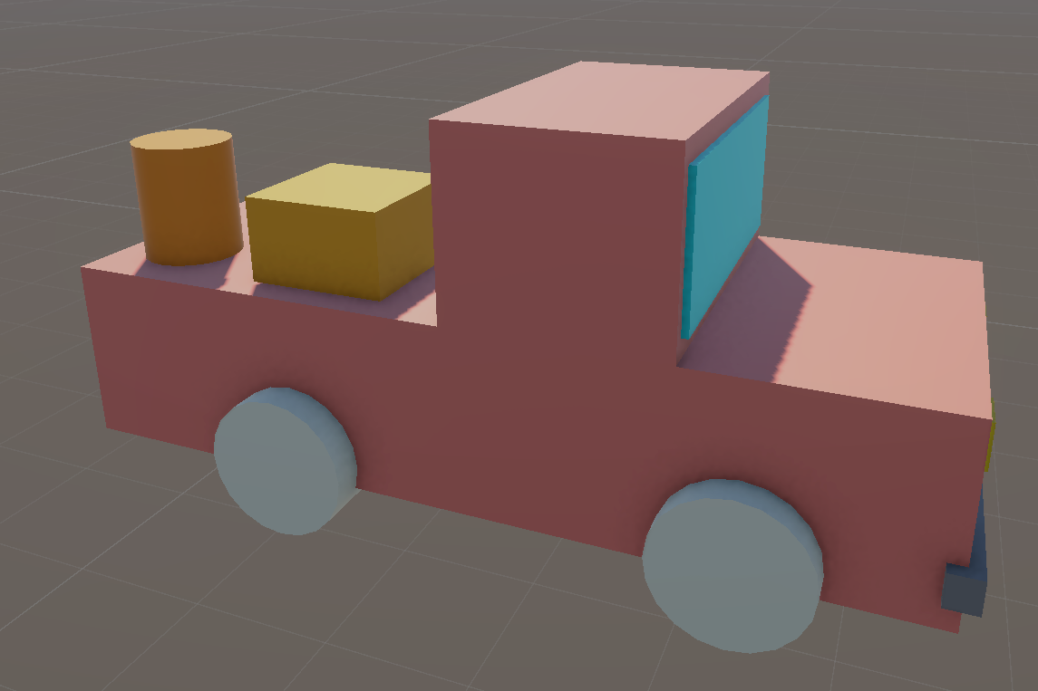
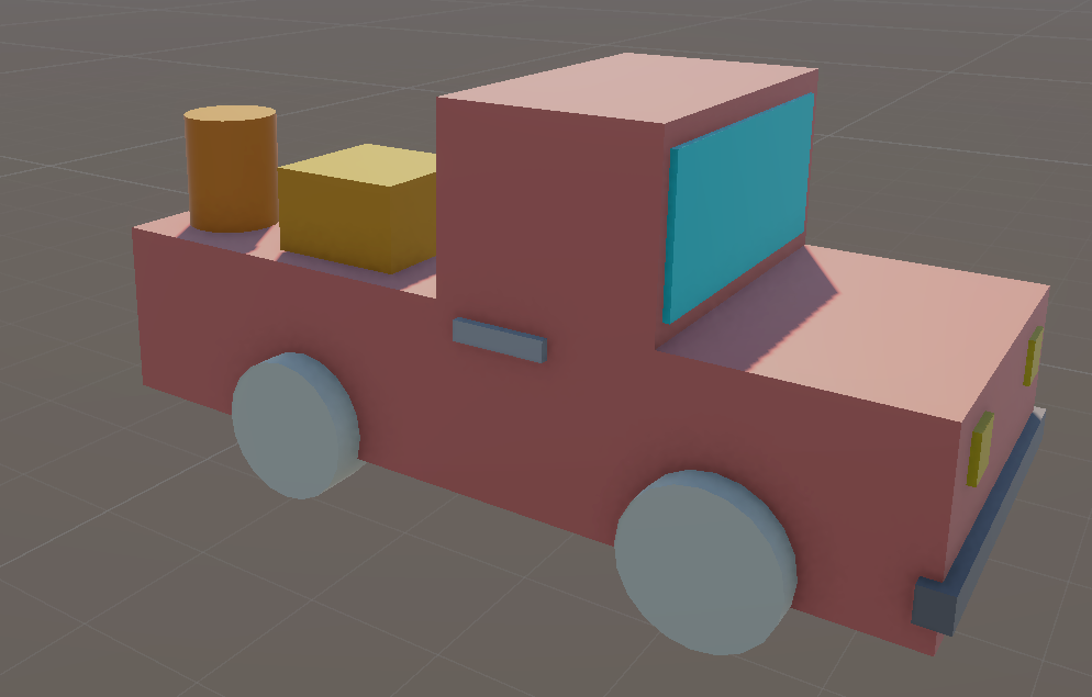
Lego Style modeling
You can refine the first approach by adding details to your model:
Two headlights
A bumper
Four wheels
A windshield
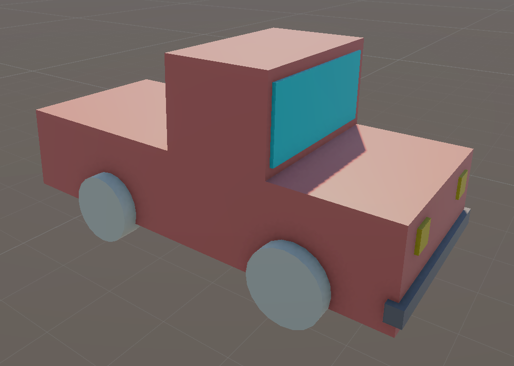
Some furniture
A door handle
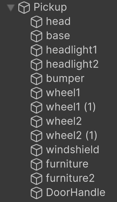
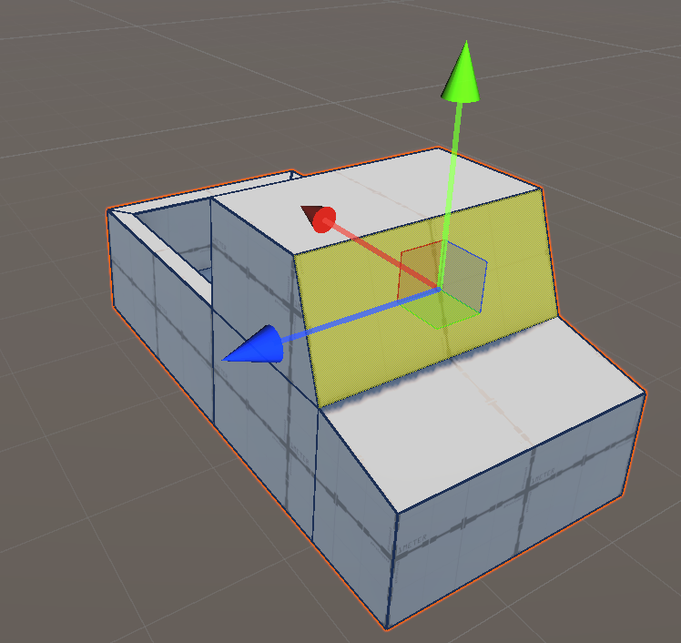
At the end, your hierarchy should look like this:
Note
We achieved the maximum that can be obtained with a LEGO-style modeling approach. If you reach this level, that’s great, and you don’t need to go any further. Level 3 is optional and intended for those who are curious to explore how things work in professional software.
Probuilder
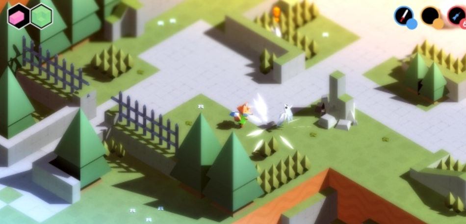
We don’t have time to cover advanced modeling software like Blender, Maya, or ZBrush. However, Unity includes a built-in modeling tool that provides essential functions for polygonal 3D modeling. It is primarily designed for level design prototyping by blocking out a level with simple geometry that can later be replaced with final game assets. That said, many professional games featuring a low-poly art style have been entirely modeled using ProBuilder, such as Secret Legend:
Since Unity 6, ProBuilder has been directly integrated into the interface. While the tools remain the same, most YouTube tutorials still showcase the older version with its dedicated workspace window.
Installation
Select Windows > Package manager
In the left column, select Unity Registry
In the search bar, type ProBuilder
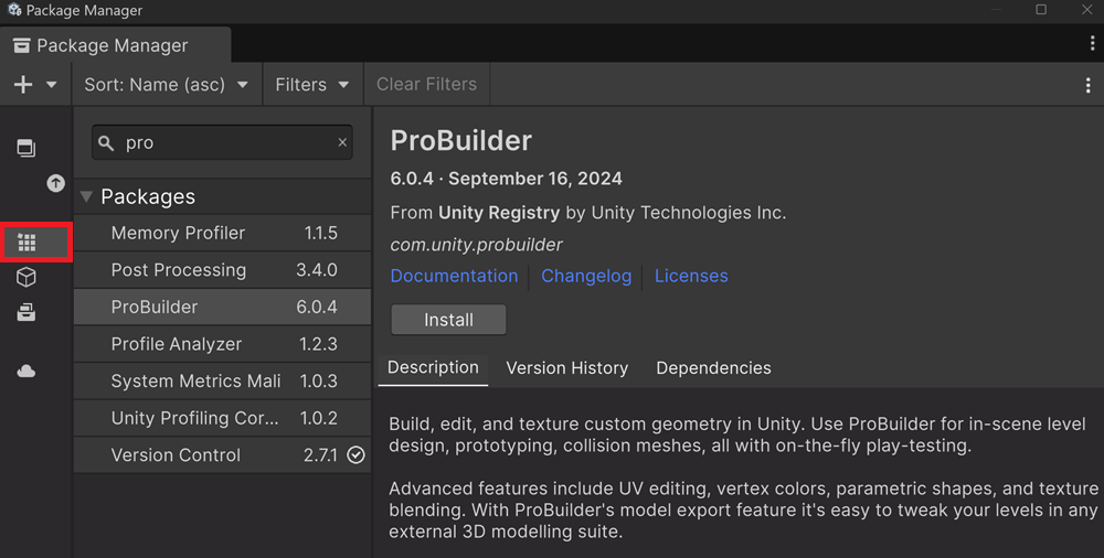
Click on the install button
First Shape
Avertissement
You must understand that a cube created with 3D Object > Cube is ABSOLUTELY not the same as a cube created with ProBuilder. The Unity standard cube is a non-modifiable instance that acts as a reference shape for all other instances in the scene. It is not editable. The only option available is to scale it to change its size in the scene, but its original shape remains unchanged. A ProBuilder cube, on the other hand, is an editable mesh that you can sculpt and modify as you wish. Each ProBuilder cube has its own unique geometry and does not share its structure with other instances.
A new tool is available: look at the cube-shaped icon
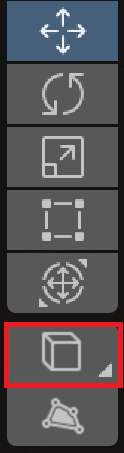
Click and old on this new button: a list of all available ProBuilder shapes appears
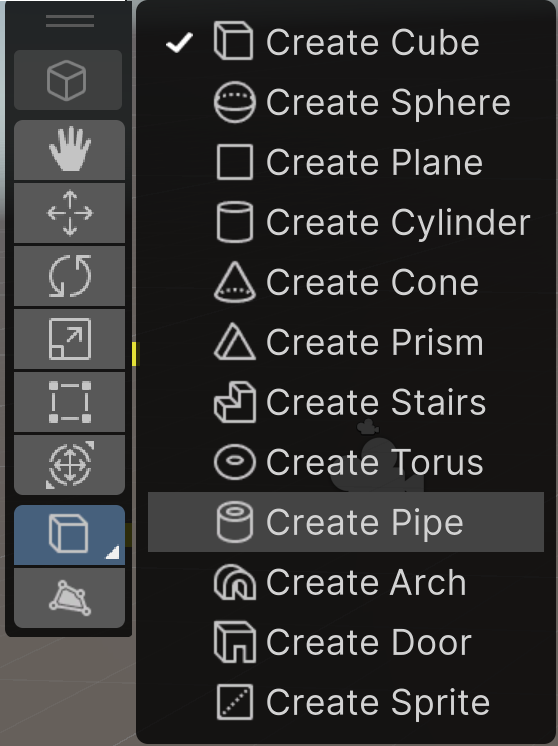
Select Create Pipe: the icon has changed
Click on the Create Pipe tool
Create a pipe in the scene
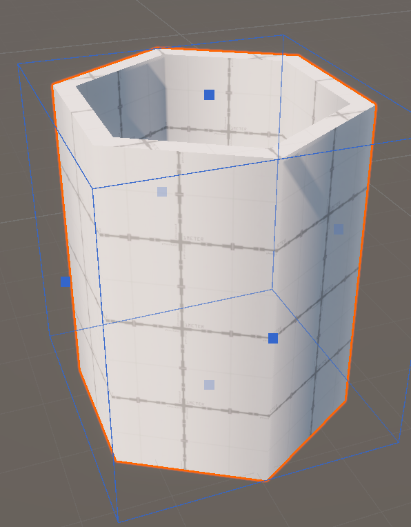
Notice that a new panel called Shape Settings appears on the lower right
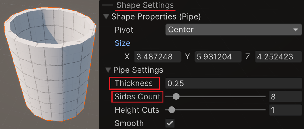
Change the Thickness parameter and see what happens
Change the Sides count parameter and loot at the shape
Change the X, Y and Z parameters and see what happens
Low poly modeling
Instead of introducing different tools independently, we demonstrate them while modeling a basic pickup.
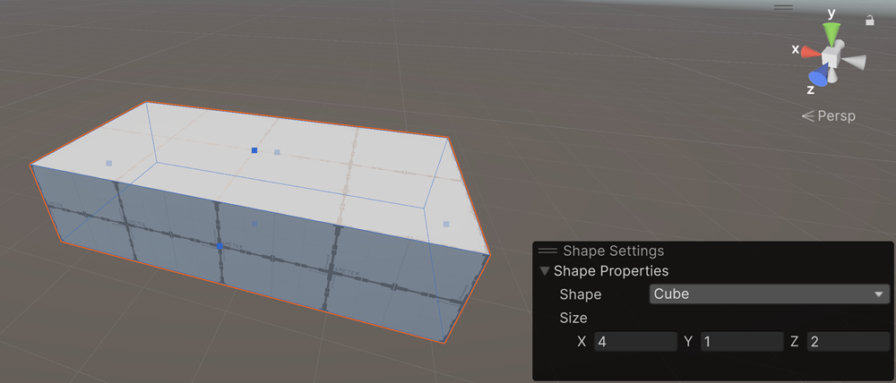
Create Cube
Create a PB cube in the scene
Change its size for X:4, Y:1, Z:2
Edge selection
Look a the grid-shape icon on the top of the toolbox panel:
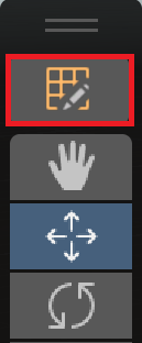
Click on this icon to activate new icons in the top bar:
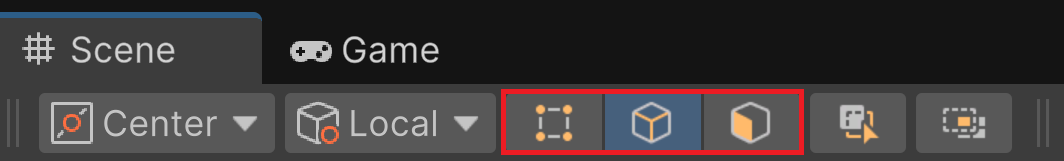
Left: select only vertices of the shape
Middle: select only edges of the shape
Right: select only faces of the shape
Activate the Edge Filter
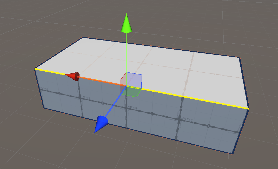
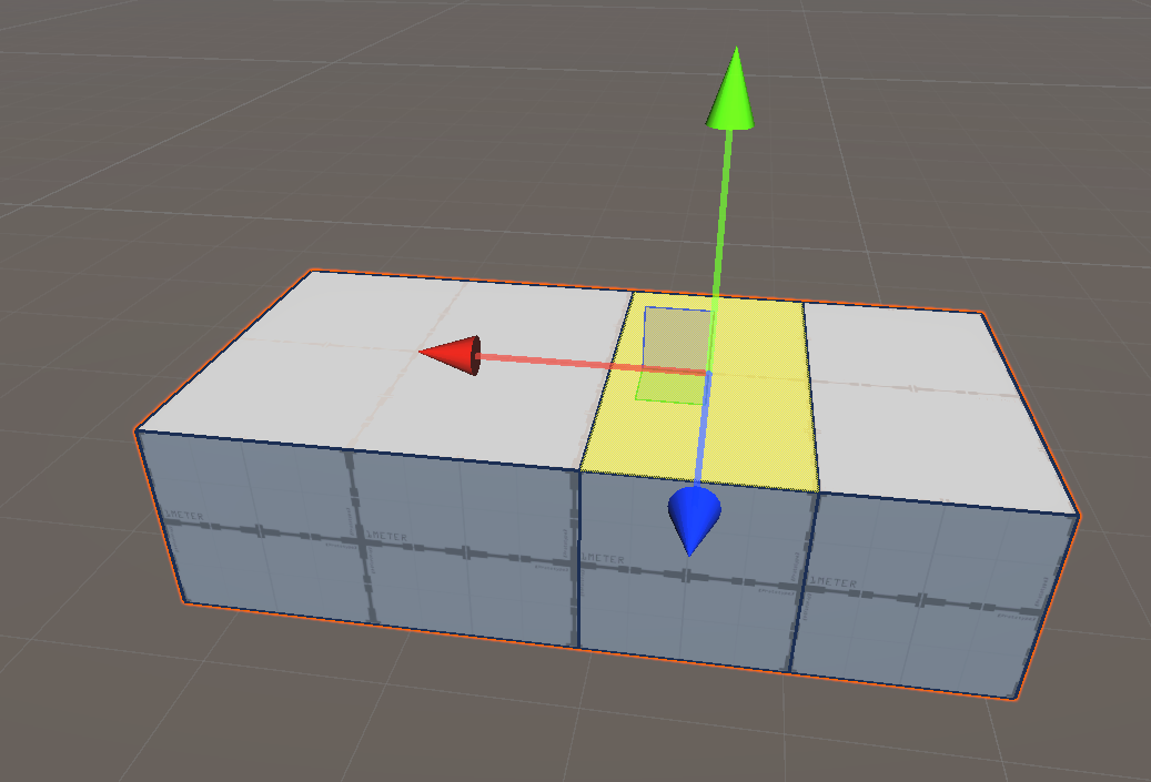
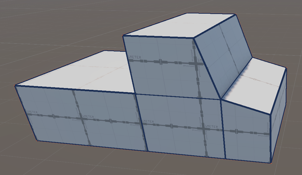
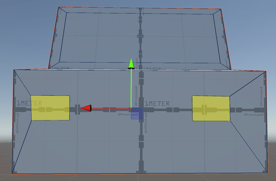
Select an horizontal edge of the cube
Edge loop
With the edge selected, right click in the scene to bring up a context panel:
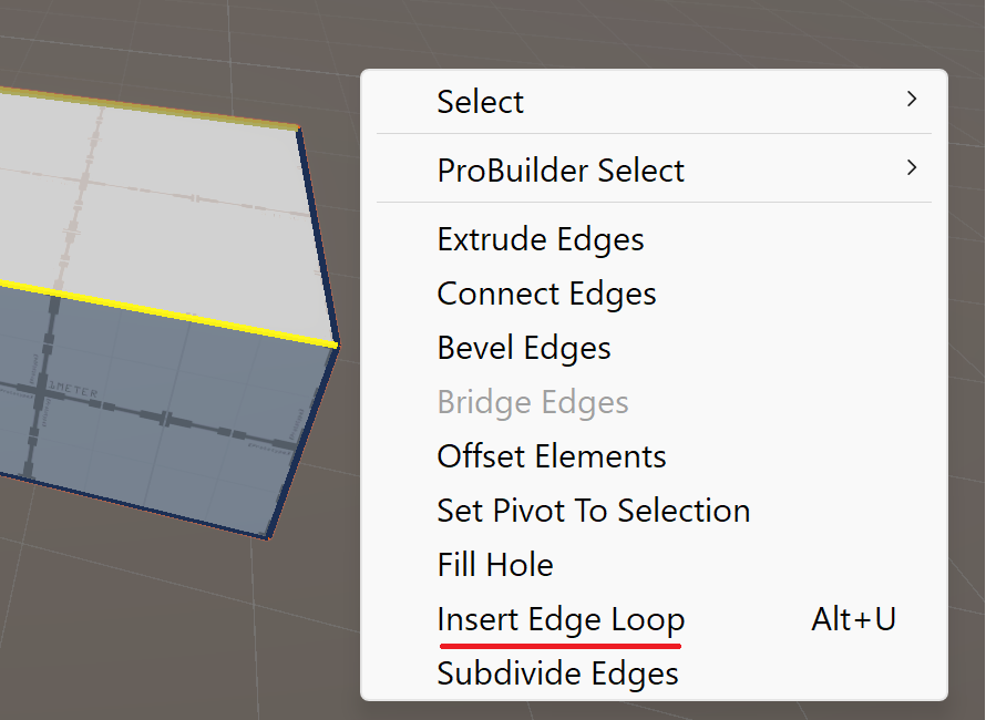
Select Insert Edge Loop, a yellow edge loop appear:
Select the red translation gizmo to move the loop at 3/4-1/4:
Click anywhere to confirm
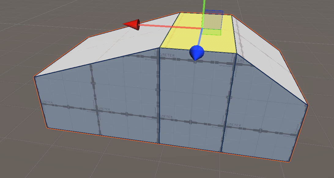
Select a long horizontal edge:
Right click and select Insert Edge Loop
With the red translation gizmo, move the loop in the middle of the shape.
Click anywhere to confirm
Face selection
Activate the Face Filter

Select the middle face on the top of the cube
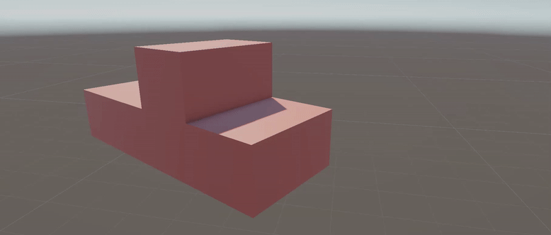
Extrusion
If we pulled the face upward using the translation tool, we would obtain this shape:
Avertissement
This is not what we are looking for. We want to add material to our object, generating new faces and edges. To do this, we need the extrusion tool.
With the face selected, right click in the scene to bring up a context panel:
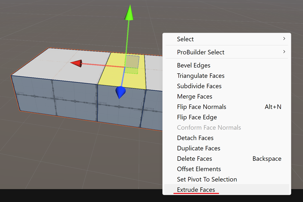
Select Extrude Faces,
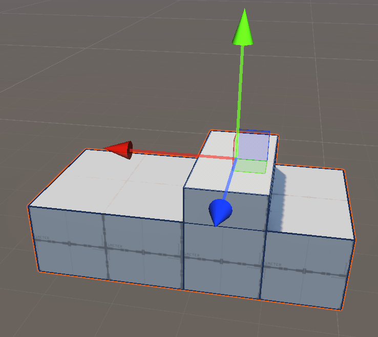
Using the green gizmo, extend the height of the pickup’s roof:
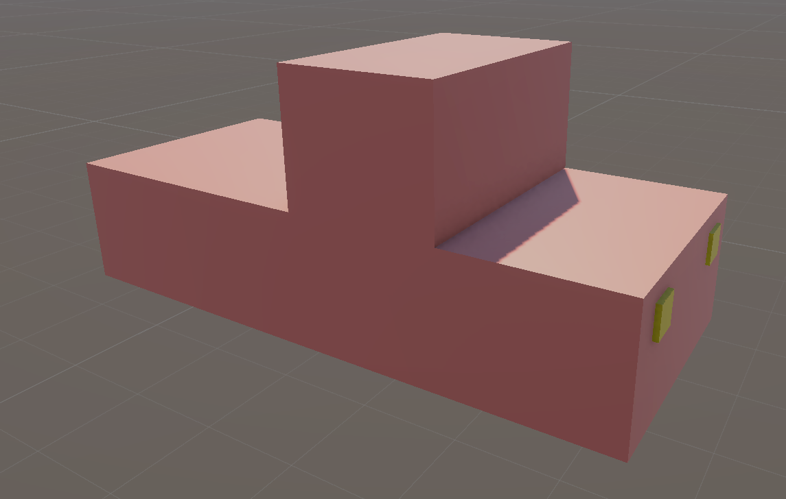
Select multiple edges
Activate the Edge Filter

Select this edge:
While holding the SHIFT key, select the three other edges:
Using the red gizmo, translate this group of edges to create a typical windshield slope
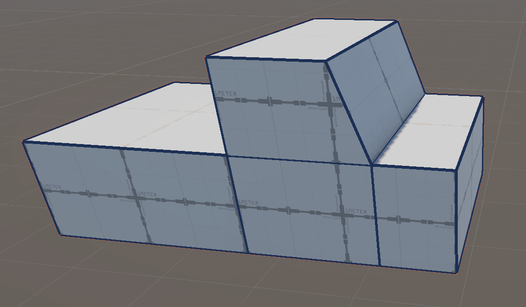
In the same way, lower the front edge of the pickup.
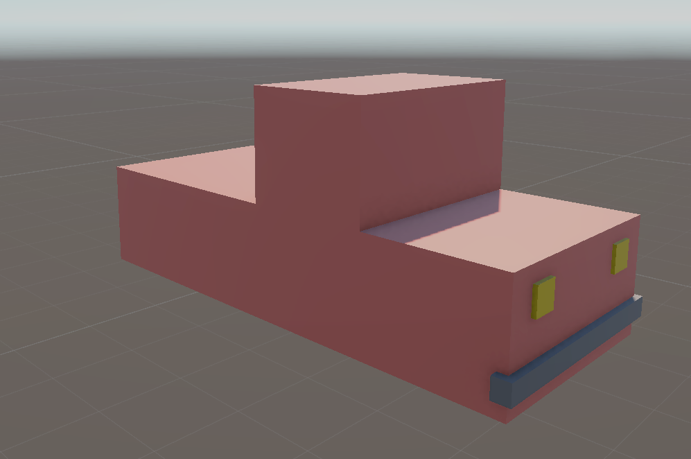
Interior extrusion
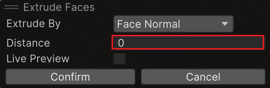
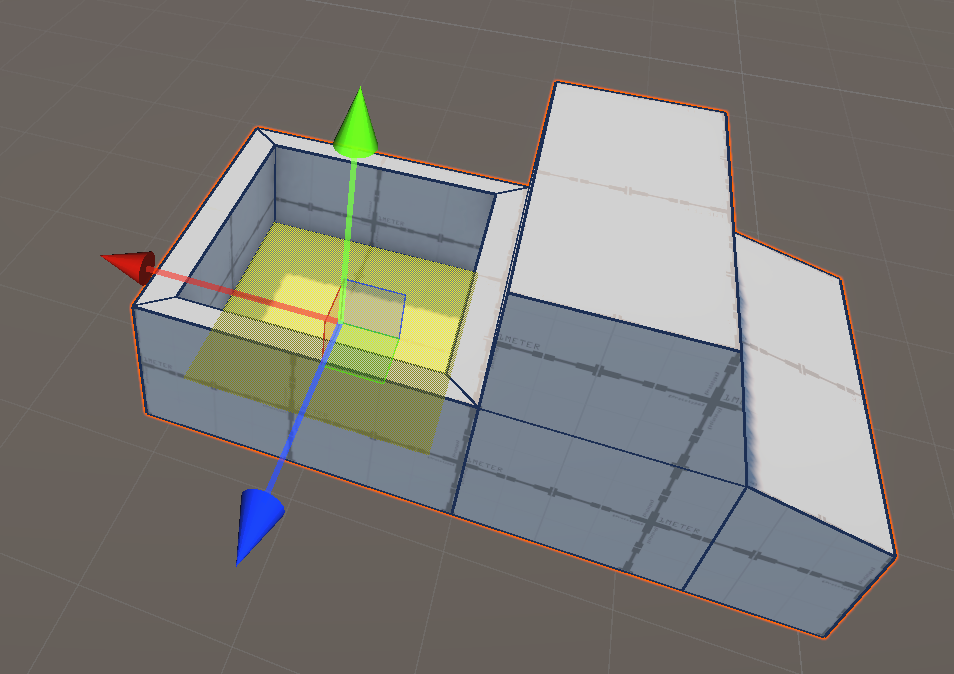
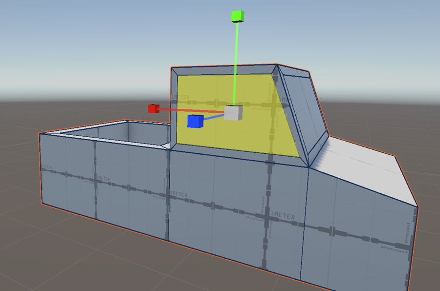
Select the face at the back of the pickup:
Right click and select Extrude Faces
Reset extrude distance to 0:
Select Scale tool in the Toolbox
Using the blue and red Gizmos, shrink the face:
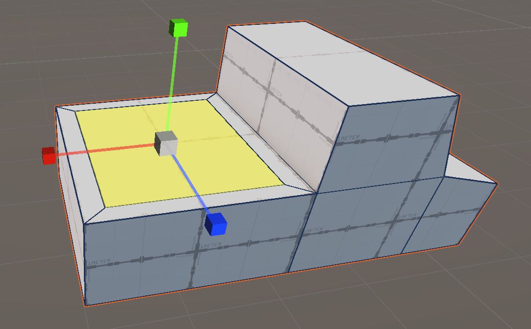
Right click and select Extrude Faces
We are performing a second extrusion
Nothing appears, do not worry
Select the Translation tool in the toolbox
Use the green gizmo to create the pickup bed:
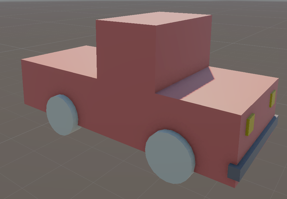
Interior extrusion
Select the windshield face
In the top toolbar, select element to obtain 3 axis oriented relatively to the windshield
The blue axis is now normal to the face
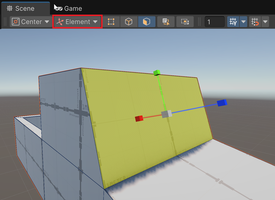
Perform an extrusion to create the glass face:
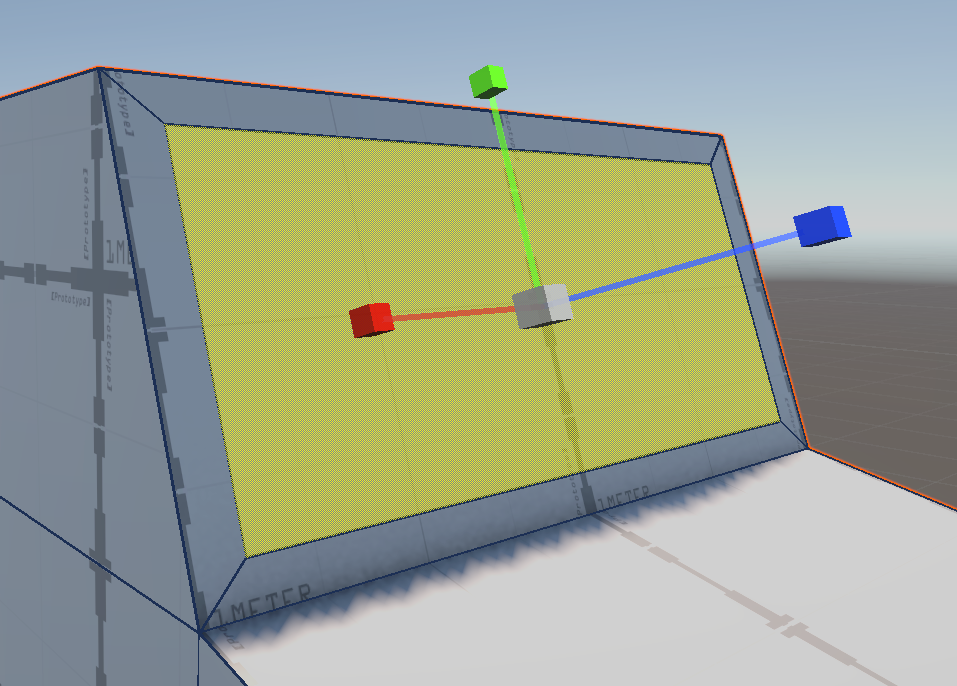
Note
Geometrically, the shape of the pickup remains unchanged. But, this new face will be used to set a specific color for the glass.
In the same way, add faces for the two side windows:
Adding edges
Loof at the front face of the pickup
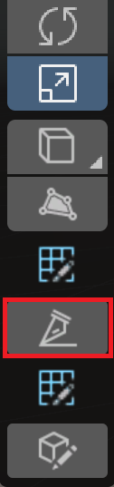
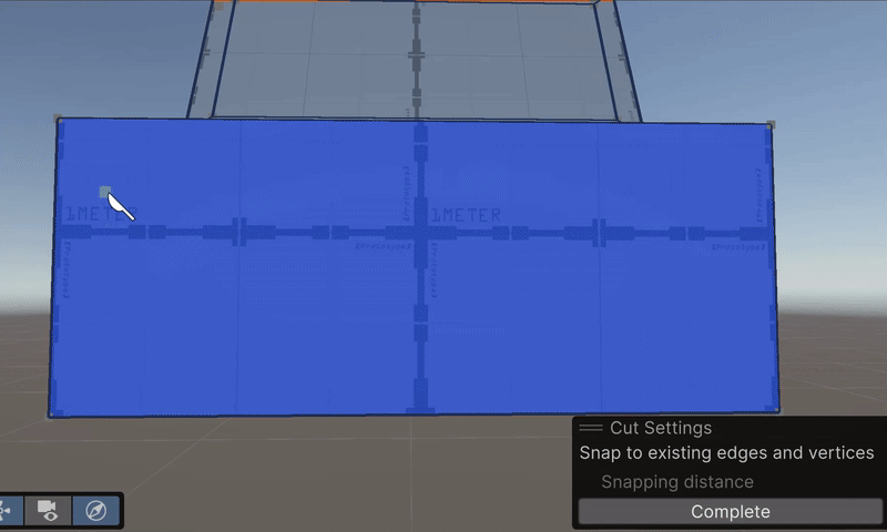
Select the Cut tool
Add edges to represent the pickup’s headlights:
Then, you can adjust vertices location to improve squareness of the headlights:
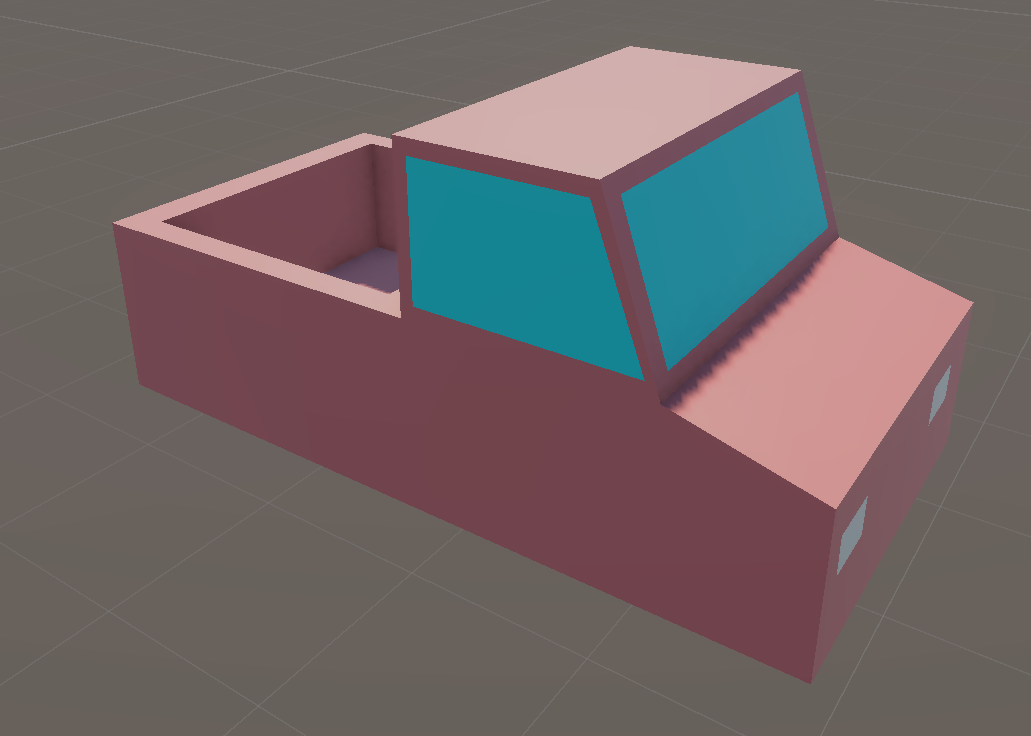
PB coloring
Neutral material
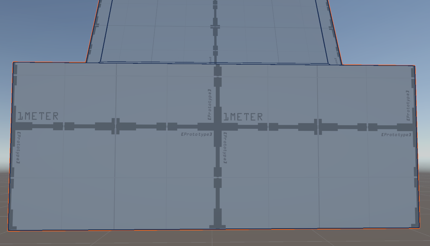
By default, ProBuilder materials use a texture featuring a 1-meter grid. We cannot disable this texture because the default ProBuilder material is read-only. Thus, we first create a copy of this material and then we will be able to modify it.
Select a standard PB oject in the scene
In the inspector, find the mesh renderer entry and click on ProBuilderDefault
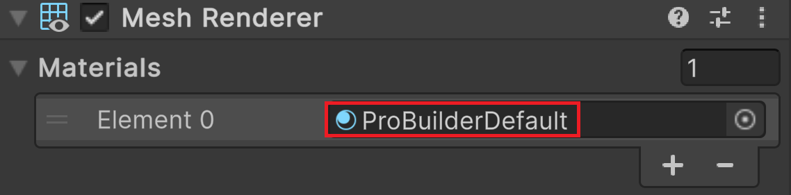
This opens the assets folder where the material is stored
Select the ProBuilderDefault material
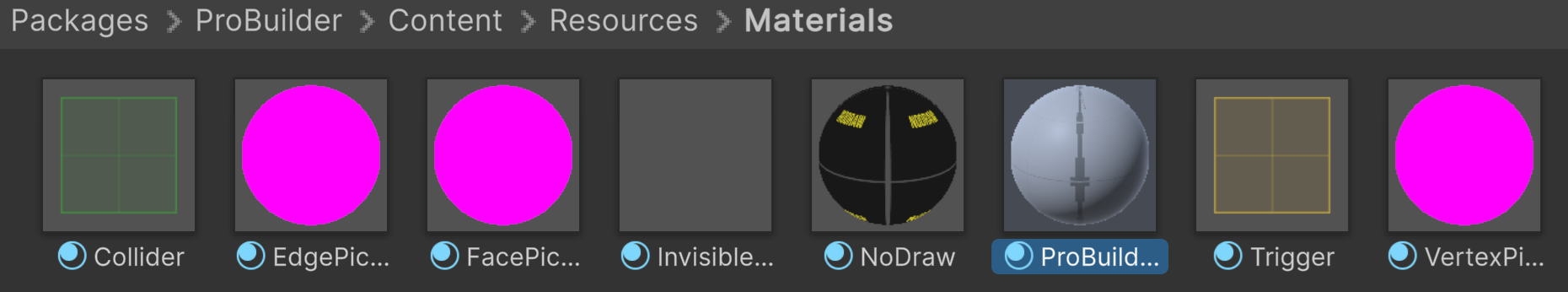
Press CTRL C to copy it
Go in the folder: Assets-SolidColorMaterial
Press CTRL V to paste it
Rename it to VColor
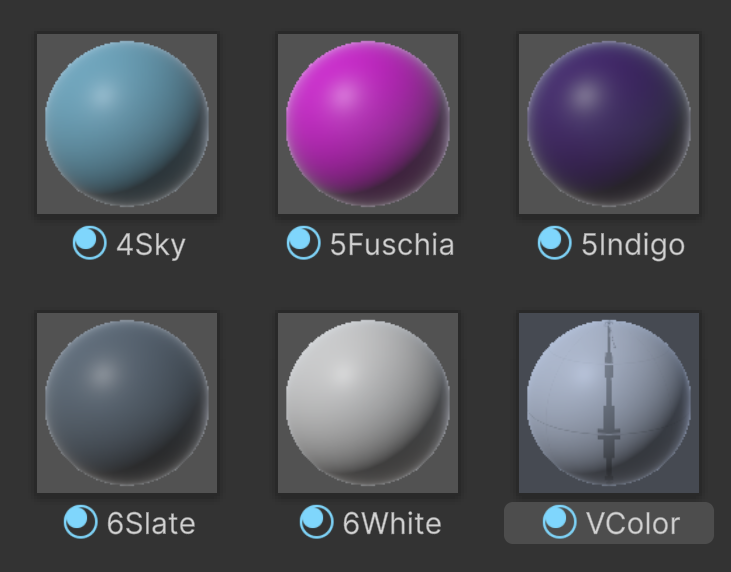
Select the VColor material
In the Inspector, on the right of the albedo parameter, click on Select button
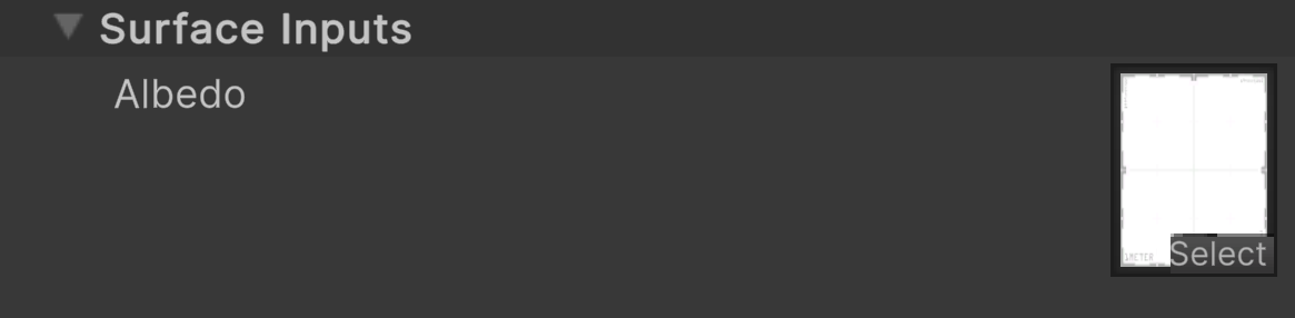
Select None (by name)
Apply this material on the pickup
Colorize
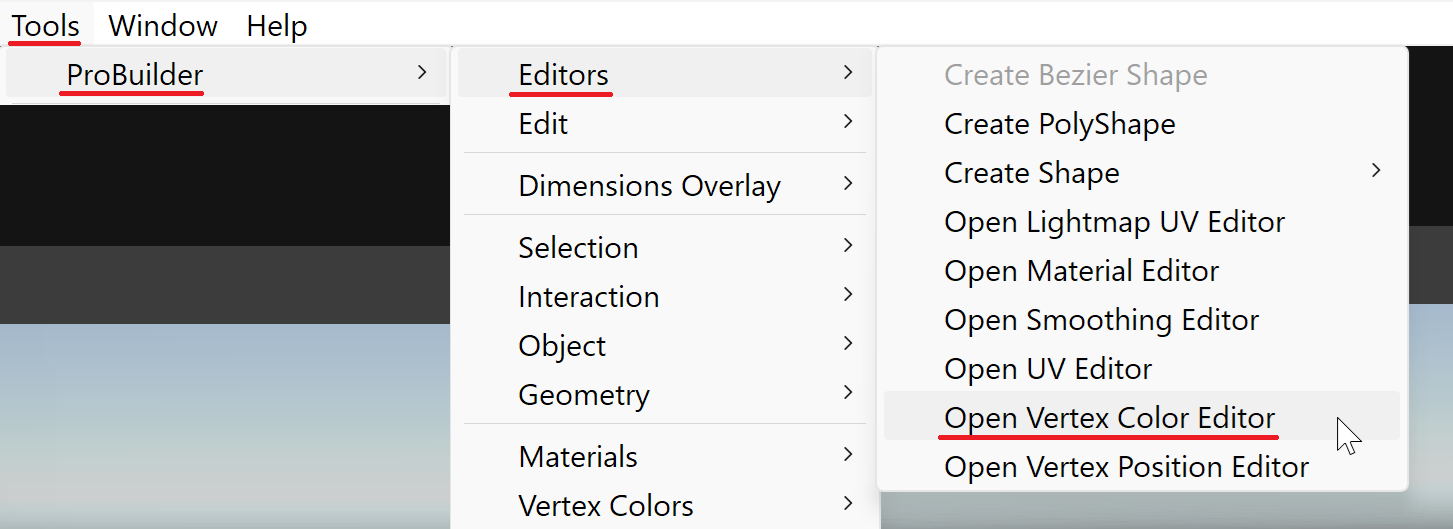
Select Tools > ProBuilder > Editors > Open Vertex Color Editor
Select Translation tool
Select the pickup
Activate Face Filter
Perform a rectangular selection to select all the faces of the pickup
Click the Apply button on the left of the brown color
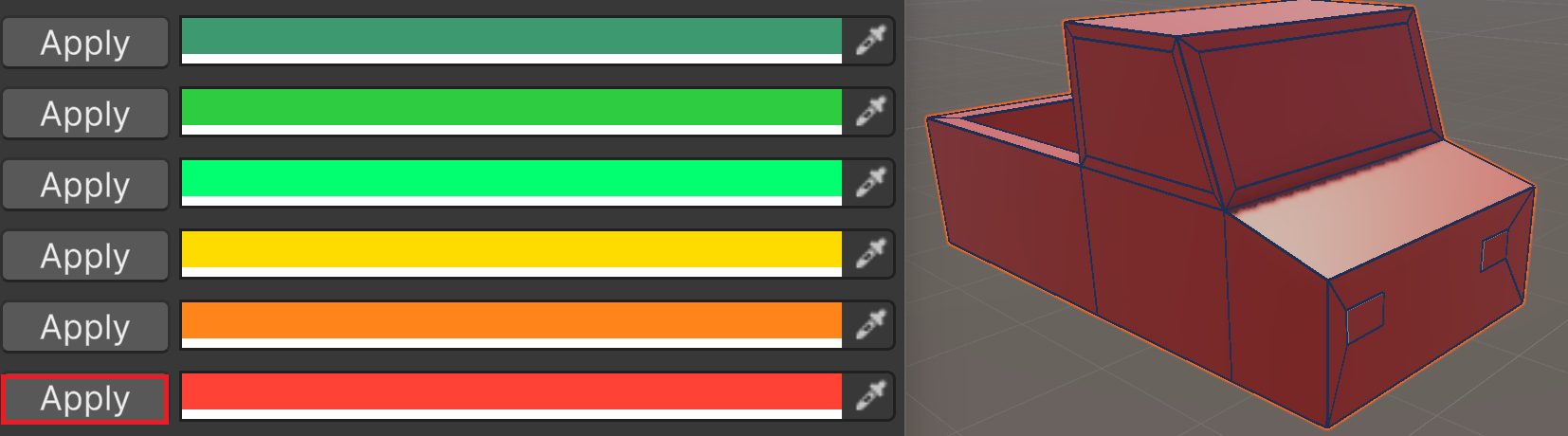
Select the windshield glass and the side windows
Choose a light blue color
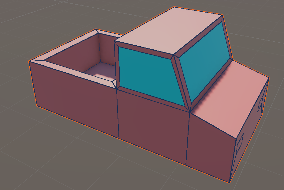
Select the pickup’s headlights
Choose a white color
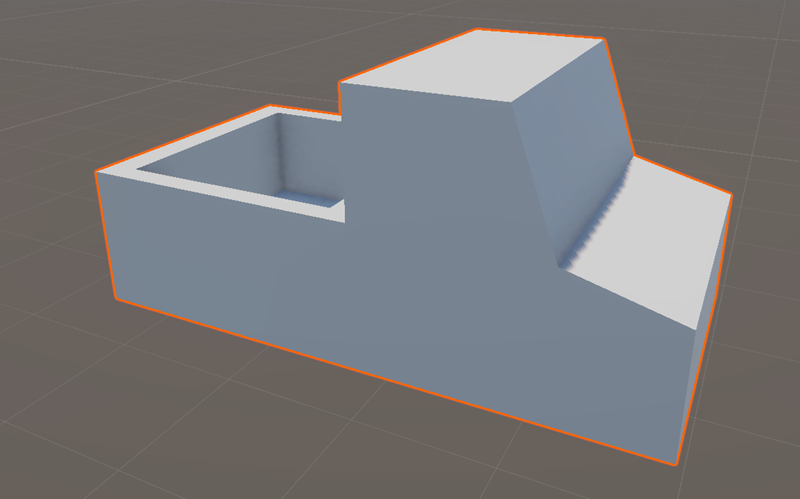
Here is our final result:
Going further
OPTIONAL - NOT PART OF THE OFFICIAL COURSE
Let’s create some pickups in few minutes:
If you want to discover what is possible with low polygonal modeling, you can visit these channels: